Wiring in a 220v outlet
I started learning how to weld as a hobby recently which has been... an experience. My first beads looked like garbage:
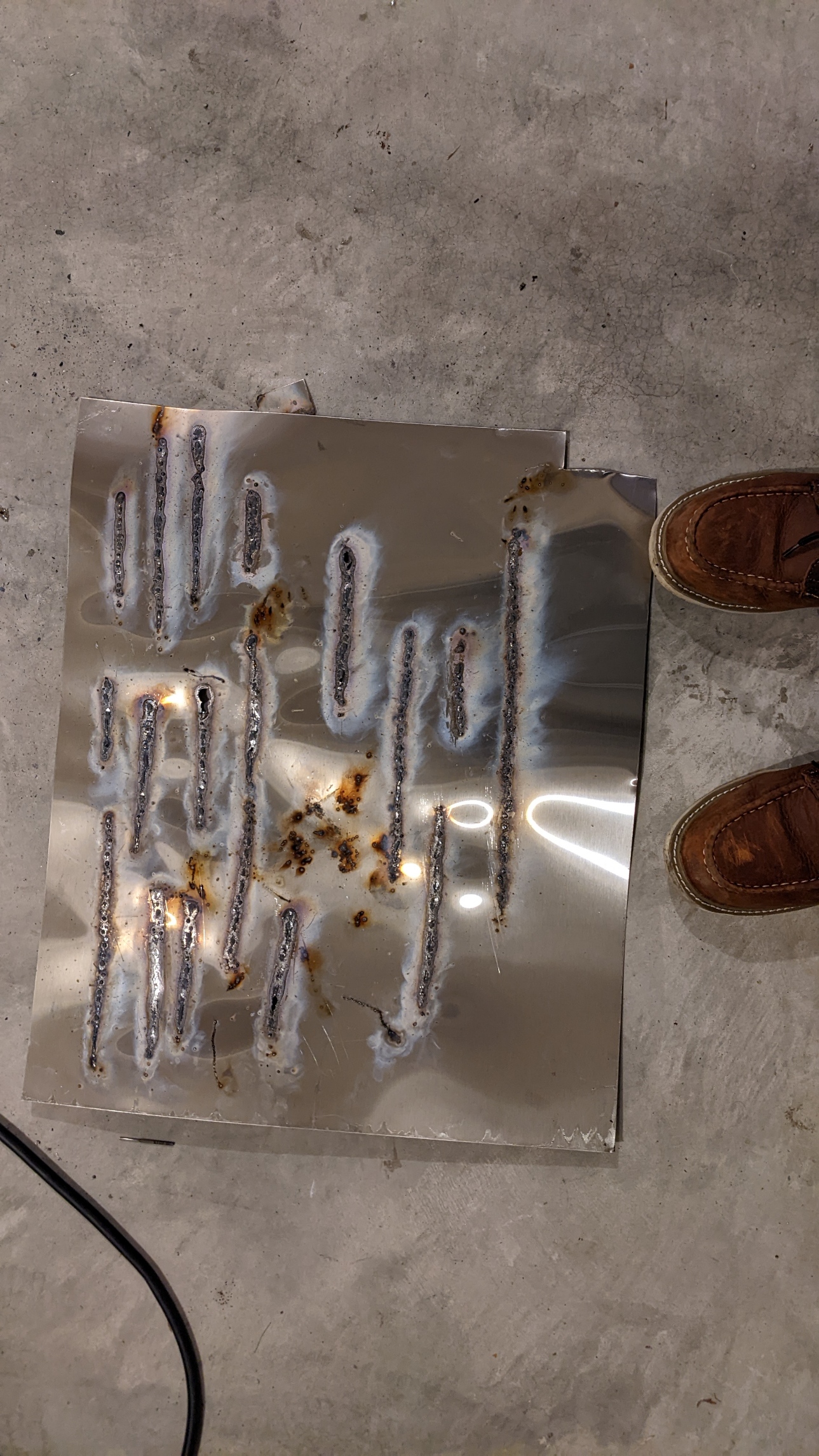
A lot of this is still just user error, but let's just say that considering I'm:
- Running my welder at 110v
- Using stick electrodes on 20 gauge sheet metal
- Using a trash can lid on my garage floor as a welding table
I'm not exactly setting myself up for success. But one problem at a time.
So let's start with the hardest one, which is getting access to a 220v outlet. Since I only plan on hooking up the one welder, I'm only adding one outlet -- keep in mind that if you're thinking about running multiple tools or appliances in your garage simultaneously, you should consider adding a separate subpanel instead to give yourself room to expand circuits while isolating everything from the main panel.
Disclaimer
I'm not a licensed electrician, nor do I know about the intracacies of your specific house or the code in your specific state or country. I'm sharing my experience purely for entertainment/educational purposes, and would recommend you refer to your local governance for code/permitting advice. Or just hire an electrician if you feel uncomfortable selecting conductors for your application or working around high-voltage circuits.
Relevant electrical codes for WA state
For WA state, your best reference for current electrical codes are via the Department of Labor and Industries (L&I): https://lni.wa.gov/licensing-permits/electrical/laws-rules-policies.
WA state references
| Document Name | Purpose | Link |
|---|---|---|
| NFPA 70 (Pub. 2020) | Baseline NEC document referenced by WA state code | Official link (or pdf if you don't want to register) |
| WAC Rule 296-4B | The WA state electrical code that inspectors will hold you to | Official link |
| L&I Permit search | If your home is newer than 2013, you can lookup electrical permits | Official link |
Can my service handle the extra load?
The first thing I checked was the capacity of my service lines and the panel. After that, I factored in the additional load from my welder to determine whether my panel could support the extra current.
Approach 1 - inspecting your conduit + breaker panel
Measure your exterior conduit
I measured the diameter of the conduit (the metal tube) feeding wire from my utility's power meter box into my main breaker panel; in my case, it was about 3 inches.
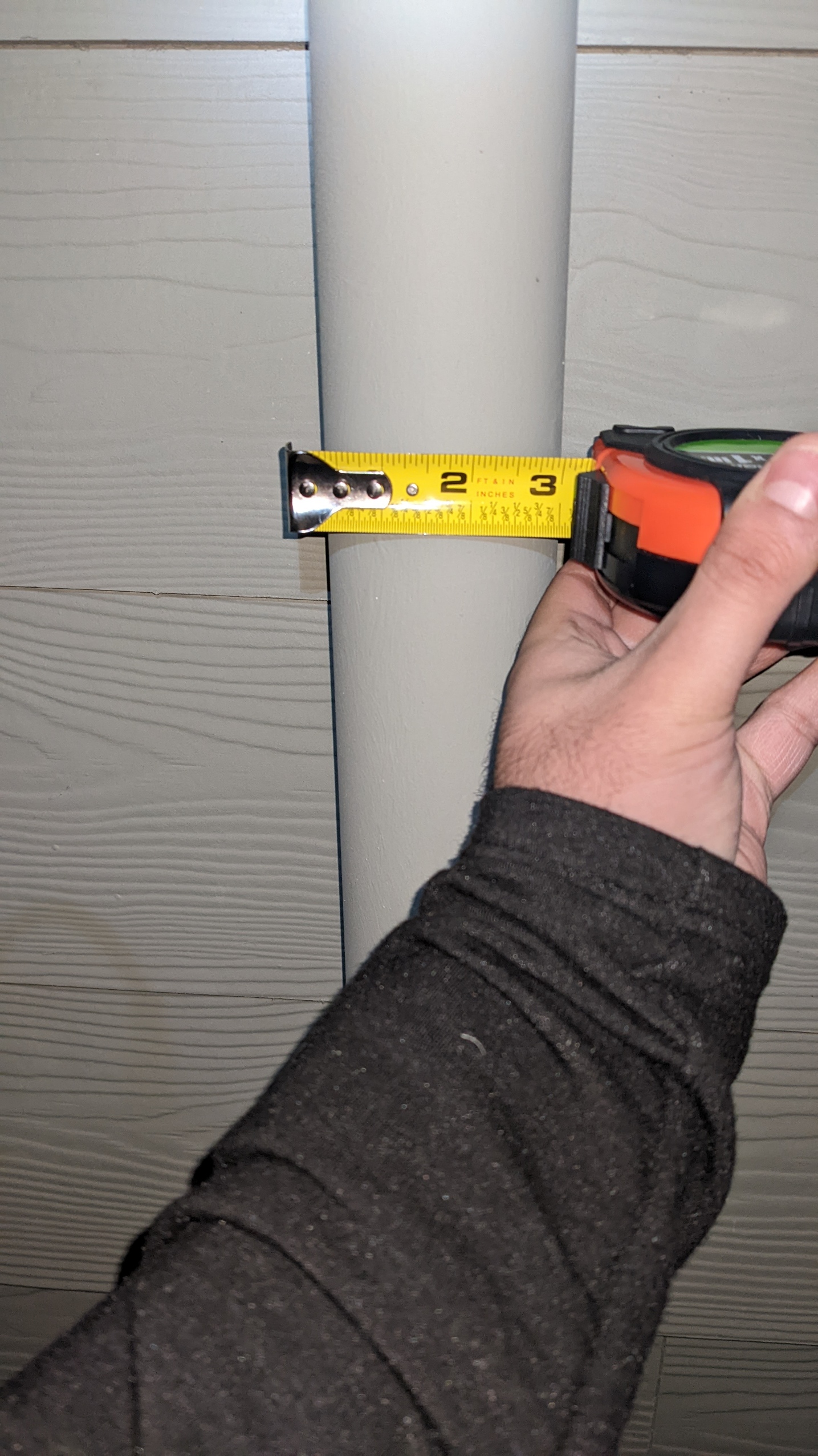
While it's possible that the utility could run thin-gauge wire inside such a large conduit, it's unlikely that they would do so. WAC 296-46B-230 §028 specifies that for 100 amp or less service (#3 AWG copper), your minimum conduit size is 1 ¼ inch, while anything above that (typically 200 amps) requires at least 2 inch conduit.
Check your main breaker switch rating
Once you've established the gauge of your service wire, check the master breaker switch in your main electrical panel. There should be one big breaker at the top of the panel -- the switch generally has a number on it which indicates the number of amps the breaker is rated for. Mine is 200, which lines up with the size of the conduit I have outside the house. So at this point I'm pretty comfortable saying my home is designed for 200 amp service.
Approach 2 - checking your permits
If your home is newer than 2013, you may be able to look up the permits for your current electrical installation from the L&I website and save you the effort of measuring everything yourself. My installation description says "NEW 200 AMP SFR" which confirms my thoughts from manual inspection.
In my case, I found the permit # from looking at the door of my breaker.
Factoring in additional load
I created a little spreadsheet to layout my current breakers and their total amperage:
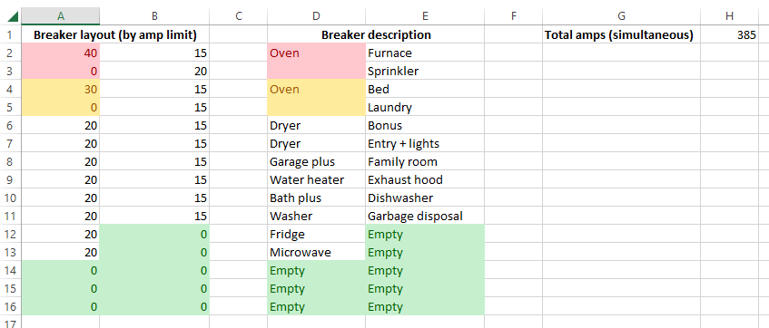
I'm sitting at 385 amps of total usage if I were to sum up all my breakers. The fact that this exceeds my 200A service rating is normal -- nobody designs a home panel expecting that literally every branch circuit is drawing peak load.
Instead you should follow the NEC guidelines for load calculations. It would take way too much time to write down the entire process, but in a nutshell the load calculation process has you walk through all your electrical appliances, general electrical usage based on the size of your home in sqft, and load factors based on how often you may use certain appliances. The end result of your calculations will give you a service rating, i.e. a realistic measure of how much continuous current your house might draw once you accommodate for which services/appliances may be in use concurrently.
Here's a particularly good example of what that might look like, straight from the NEC code:
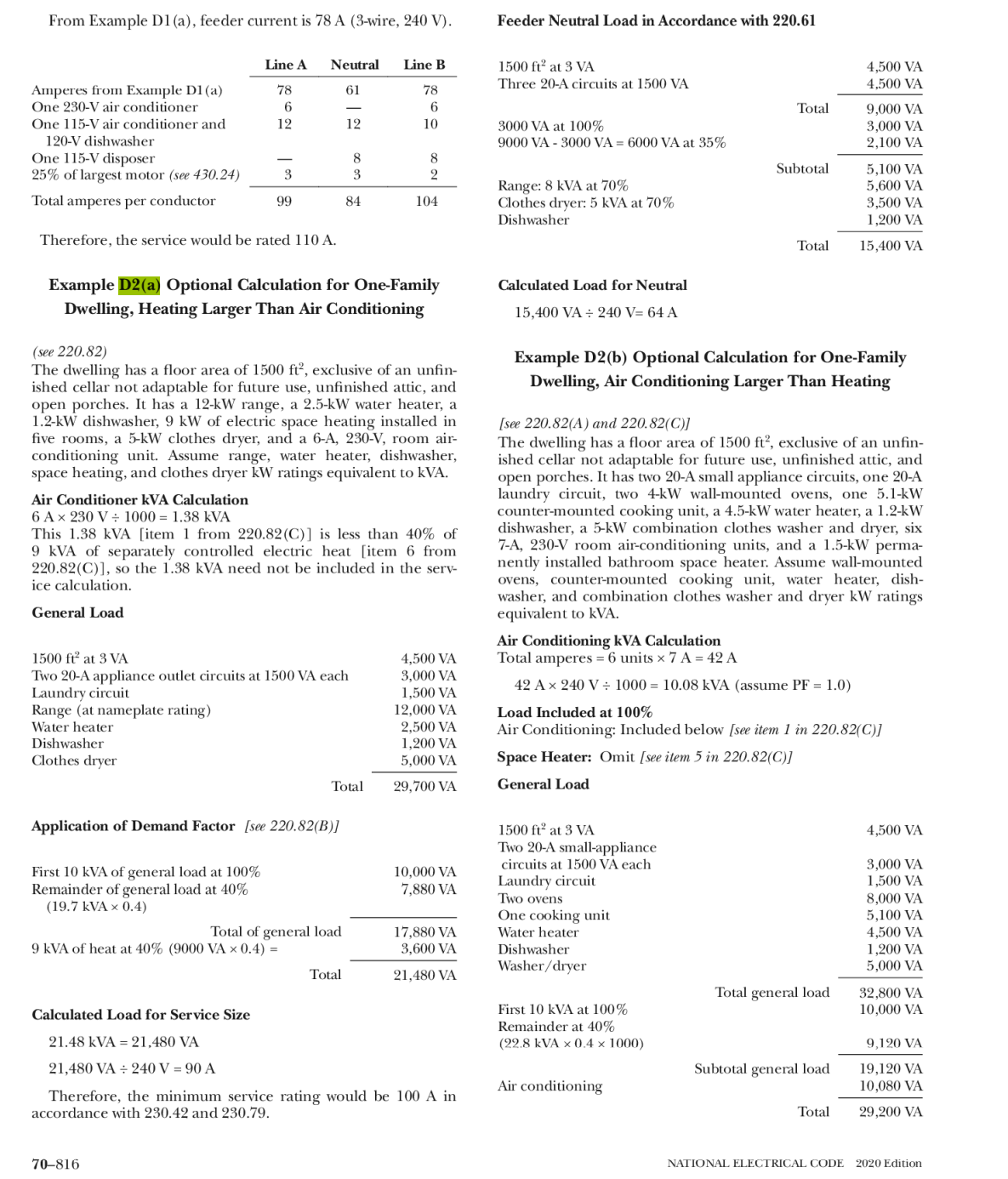
NOTE: There are two ways to do load calcs: via the Standard Method or the Optional Method. Do not use the Optional Method if your home's feeder is <= 100 A.
And some other links I found helpful as I worked through those calculations, mostly walking through example homes:
- Walkthrough of the Optional Method for load calcs (youtube)
- Determining load capacity for a branch circuit
- Example of the Optional Method for load calcs
- Yet another load calc example
- WA Homeowner's Residential Electrical Inspection Guidelines
It should go without saying... but keep in mind that none of these are substitutes for analyzing your own breakers and appliances. For example, a lot of these walkthroughs a minimum number of small-appliance circuits or a derating factor of 75% based on a set number of kitchen appliances, but these are sourced from derating levels in the NEC code which may not necessarily apply if you have more small appliance circuits or fewer kitchen appliances. What I found the most helpful was using the first youtube link to identify points in the NEC code that apply to typical load calcs, then reading them myself in the NEC guidelines and comparing that against my breaker setup to ensure I was using the correct rules and demand factors. From there cross-checking against the examples in NEC Annex D (see the image earlier) helped me sanity-check that I was accounting for all of my circuits correctly.
After working through that process, I found that my baseline service load is 122 A -- well below the 200 A service input I already have. Even after factoring in a dedicated welder pulling wayyy more current than what my welder actually would sink, my service current comes up to 172 A which gives me plenty of margin. All of this is to say that with a 200 A supply I have high confidence that I can run a 50A welder circuit on top of what I already have. If you have e.g. a 100 or 150 A service, I'd probably recommend hiring an electrician to get 200 A service to ensure your house can accommodate the extra load with room to spare.
Selecting Parts
Selecting wiring
I need to read more about types of wiring, e.g. THHN vs. NM-B (Romex), solid and stranded for this application, etc. Long story short though it seems THHN is more heat resistant with its nylon insulation, and if I'm running a 50 A welding circuit, I'd probably want to go for a 6 AWG cable to make sure my wires have no chance of overheating. I found this link on ampacity charts to be particularly useful because it also covers the thermal rating for each wire type. With 6 AWG being rated for 55A of continuous current that should be more than sufficient for a welding circuit, or even something like a level 2 EV charger.
I'm using 6/2 Romex (NM-B) because it is simple to wire, cost-effective, and still rated to sustain my use case with no real concerns. I'm using 6/2 instead of 6/3 because I decided I do not need a neutral wire for a 120V supply -- just the 2 hots and a ground. I don't ever intend to connect 120V devices to my ciruit.
Selecting a plug
I installed a NEMA 6-50R receptacle, since my plug is NEMA 6-50 and I can't imagine having a need for the 120V. I don't wanna spend an extra 50 bucks on adapters for my welder (or have extra failure points, either).
- https://www.homedepot.com/p/Leviton-50-Amp-Double-Pole-Single-Outlet-Black-R20-05378-P00/311373590
- https://www.homedepot.com/p/Leviton-50-Amp-2-Pole-Flush-Mount-Shallow-Single-Outlet-Black-NEMA-6-50R-R10-05374-S00/300324220
I've heard bad things about the Leviton's plug/unplug cycle life which has caused arcing across some of the internal spring contacts due to the springs wearing out and no longer having tight connections on the plugs. A better receptacle to use would be a Hubbel industrial contact. The reason I still am using the Leviton contact is because I am avoiding constantly plugging and unplugging my devices to begin with, and while I'm using the outlet I'll be working very close to the breaker so I can shut things off quickly in an emergency anyways.
Selecting a breaker
To be compliant with NEC code I am using a 50-amp GFCI breaker. GFCI branch protection is required for garage and kitchen circuits, and because there's no such thing as a GFCI NEMA-50 receptacle I have to provide that protection at the breaker.
Selecting conduit
When you are selecting conduit think about:
- The NEC code's conduit fill requirements1
- How easy it is for you to work with for the tools you have and the run you have
- How much protection you need in the environment the cable is in.
I opted for 1" EMT conduit, which is pretty overkill, but provides ample room for the cable to run without overheating and makes the cable less likely to get caught or damaged while it's getting pulled. It was a PITA to bend though so I'd recommend using 3/4" EMT in the future (or a flex conduit), especially if you're doing longer runs like across a garage or something.
Footnotes
- Conduit fill is typically based on loose connectors like THHN, not Romex. You should treat Romex as a single conductor based on the outer jacket thickness. For 6AWG Romex using a 0.029 diameter you'd need at least 0.5" diameter EMT conduit. ↩